You're quite welcome. First a correction: TP13 is the 1.0V power rail for the Zynq, not the Epiphany, so it doesn't help this question. However, as soon as I clicked "submit" on that last post I had a thought. Even though R330 is "officially" a zero-ohm resistor, it will have some finite resistance. I just measured the voltage drop across R330, it's hard to do directly but easy to do by probing the "bottom" pin of C248 and the "top" pin of C218. Here is a picture of the area of the board I'm talking about, between the Epiphany and the text "Parallella-I", near U30:
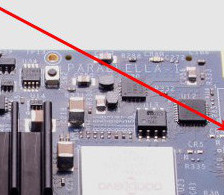
- Board region near U30 (not U29!)
- U29area.jpg (17.38 KiB) Viewed 15010 times
And here is a diagram showing the locations to probe. This is not as dangerous as taking a soldering iron to your board or adding external power supplies, but it is still possible to damage the board if a probe slips and shorts something out, so I am only suggesting this to those who are confident enough to do it at their own risk. Please be extra careful!
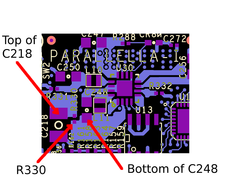
- CoreCurrentMeasure.png (93.29 KiB) Viewed 15010 times
The issue is now one of calibration, I don't expect the effective resistance between those points to be very consistent between boards, but if you want to get a rough idea of proportionally how much change there is to the power consumption between different Epiphany algorithms then this migh be useful. For example, I measure 3.5mV with the Epiphany idle, 6.8-7.0mV running the Mandelbrot demo, and also 6.8-7.0 running blobubska, so I can say that those two applications use roughly the same amount of core power. I just can say how much power that is.
If you want an actual current (and therefore power) measurement you'll have to calibrate that resistance by sinking a known amount of current after R330 and measuring the change in the voltage drop. Don't use the same probe to pull the current and make the voltage measurement!
This could be interesting.
